All you need to know about hall effect current sensors
In this artical, we are introducing hall effect current sensors, which are widely used for industrial current measurement due to their effective cost and performances. The contents about hall effect, how do hall effect current sensors work, the applications, advantages and disadvantages, as well as how to use hall effect current sensors properly.
Table of Contents
What is Hall Effect?
When was Hall Effect discovered, and how does it work?
The Hall effect was discovered by the American physicist Hall in 1879. When a current passes through a conductor in a magnetic field, a potential difference perpendicular to the direction of the current and the direction of the magnetic field will be generated in the conductor. And the magnitude of the potential difference is proportional to the vertical component of the magnetic induction and the magnitude of the current. In semiconductors, the Hall effect is even more pronounced.
The Hall effect is essentially the deflection of moving charged particles in a magnetic field caused by the Lorentz force. When charged particles (electrons or holes) are confined in a solid material, this deflection leads to the accumulation of positive and negative charges in the direction perpendicular to the current and magnetic field, thereby forming an additional transverse electric field, that is, the Hall electric field EH.
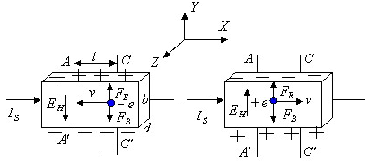
The current IS passes through the N-type or P-type Hall element, the direction of the magnetic field B is perpendicular to the direction of the current IS, and the direction of the magnetic field is from the inside to the outside. For N-type semiconductors and P-type semiconductors, the generated directions are as shown in the Hall on the left and right. Electric field EH (according to this, the properties of the Hall element can be judged – N-type or P-type).
The Hall potential difference EH prevents the carriers from continuing to shift to the side. When the transverse electric field force FE and the Lorentz force FB experienced by the carriers are equal, the accumulation of charges on both sides of the Hall element reaches a dynamic balance.
because:
FE=eEH, FB=evB,
therefore:
eEH=eVB (1)
Suppose the width of the sample is b, the thickness is d, and the carrier concentration is n, then:
IS=nevbd (2)
From formulas (1) and (2), we can get:
Hall potential difference UH=EHb=(1/ne)(ISB/d)=RH(ISB/d)
RH=1/ne is the Hall coefficient of the material, which is an important parameter reflecting the strength of the Hall effect of the material.
For a fixed Hall element, the thickness d is fixed, and KH is the Hall coefficient of the Hall element, which can be obtained:
UH=KHISB (3)
That is: the Hall potential difference UH is proportional to the current IS and the magnetic induction B.
Applications of Hall Effect
Using the Hall effect, switch sensors and linear sensors can be made. Switch-type Hall sensors are widely used in position, displacement and speed measurement, and linear Hall sensors are widely used in the measurement of magnetic field, current and voltage.
In recent years, there is an increasing demand for the measurement of variable-frequency electricity with non-power frequency and non-sinusoidal characteristics. Due to the narrow frequency application range of electromagnetic transformers, in comparison, the applicable frequency bands of Hall voltage and current sensors Wide, and can be used for DC measurement, its market prospect is broad.
However, for the accurate measurement of variable frequency power in a complex electromagnetic environment, due to the sensitivity of the Hall sensor to the magnetic field, special attention should be paid to the application. In addition, because Hall voltage and current sensors are mainly used for voltage and current measurement for control purposes, manufacturers generally do not provide angle difference indicators that are critical to power measurement. For occasions that require accurate power measurement, use them with caution.
The National Frequency Conversion Power Measuring Instrument Metrology Station has conducted spot checks on some common types of Hall voltage and current sensors. At 50Hz, the angle difference index is between 20′~240′, compared with 10′ of the 0.2-level electromagnetic transformer. In other words, the angular difference index is poor, and for occasions with low power factor, it has a great influence on the accuracy of power measurement.
How Do Hall Effect Current Sensors Work and Types
Summary of Hall Effect Current Sensors
Hall current sensors include open-loop and closed-loop types. Most of the high-precision Hall current sensors are closed-loop. The closed-loop Hall current sensor is based on the magnetic balance Hall principle, that is, the closed-loop principle. When the primary current IP generates The magnetic flux is concentrated in the magnetic circuit through the high-quality magnetic core, the Hall element is fixed in the air gap to detect the magnetic flux, and the reverse compensation current is output through the multi-turn coil wound on the magnetic core, which is used to offset the generation of IP on the primary side The magnetic flux, so that the magnetic flux in the magnetic circuit is always kept at zero. After being processed by a special circuit, the output terminal of the sensor can output a current change that accurately reflects the current of the primary side.
How Does Hall Effect Current Sensors Work
Open-loop Hall Effect Current Sensors
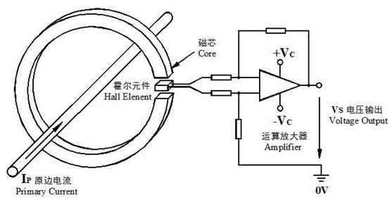
When the primary current IP flows through a long wire, a magnetic field will be generated around the wire. The magnitude of this magnetic field is proportional to the current flowing through the wire. The generated magnetic field gathers in the magnetic ring and passes through the air gap of the magnetic ring. The Hall element measures and amplifies the output, and its output voltage VS accurately reflects the primary current IP. The general rated output is calibrated to 4V.
Magnetic Balance (Closed Loop) Hall Effect Current Sensors
When the primary current IP flows through a long wire, a magnetic field will be generated around the wire. The magnitude of this magnetic field is proportional to the current flowing through the wire. The generated magnetic field gathers in the magnetic ring and passes through the air gap of the magnetic ring. The Hall element measures and amplifies the output, and its output voltage VS accurately reflects the primary current IP. The general rated output is calibrated to 4V.
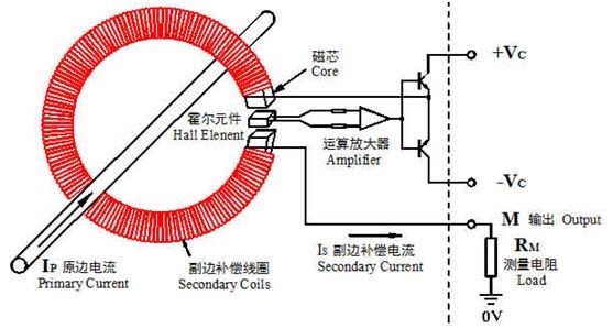
The magnetic balance current sensor is also called a compensation sensor, that is, the magnetic field generated by the primary current Ip at the magnetic gathering ring is compensated by the magnetic field generated by a secondary coil current, and the compensation current Is accurately reflects the primary current Ip, thus Make the Hall device in the working state of detecting zero magnetic flux.
The specific working process is: when a current passes through the main circuit, the magnetic field generated on the wire is gathered by the magnetic ring and induced to the Hall device, and the generated signal output is used to drive the power tube and make it conduct, thereby obtaining a compensation Current Is. This current passes through the multi-turn winding to generate a magnetic field, which is exactly opposite to the magnetic field generated by the measured current, thus compensating the original magnetic field and gradually reducing the output of the Hall device. When the magnetic field generated by multiplying Ip and the number of turns is equal, Is will no longer increase. At this time, the Hall device plays the role of indicating zero magnetic flux. At this time, Ip can be tested by Is. When Ip changes, the balance is destroyed, and the Hall device has a signal output, that is, the above process is repeated to achieve balance again. Any change in the measured current will upset this balance. Once the magnetic field is out of balance, the Hall device has a signal output. After the power is amplified, a corresponding current flows through the secondary winding immediately to compensate the unbalanced magnetic field. From the magnetic field imbalance to the balance again, the time required is theoretically less than 1μs, which is a dynamic balance process. Therefore, from a macro point of view, the ampere-turns of the secondary compensation current are equal to the ampere-turns of the primary measured current at any time.
The main difference between closed-loop Hall current sensor and open-loop Hall current sensor
A. Bandwidth difference
Microscopically speaking, the magnetic field at the air gap always changes near zero flux. Since the magnetic field changes very little, the changing frequency can be faster. Therefore, the closed-loop Hall current sensor has a fast response time. The actual closed-loop Hall current sensor bandwidth can usually reach more than 100kHz. The bandwidth of the open-loop Hall current sensor is usually narrow, such as: the bandwidth of the common open-loop Hall current sensor is about 3kHz.
B. Difference in precision
The output of the secondary side of the open-loop Hall current sensor is proportional to the magnetic induction intensity at the air gap of the magnetic core, and the magnetic core is made of high magnetic permeability materials. Non-linear and hysteresis effects are inherent characteristics of all high magnetic permeability materials. Therefore, the open-loop Hall current sensor generally has a poor linearity angle, and the output of the secondary side will be different when the primary side signal rises and falls. Open-loop Hall current sensor accuracy is typically worse than 1%. Since the closed-loop Hall current sensor works in the zero-flux state, the non-linearity and hysteresis effect of the magnetic core will not affect the output, and better linearity and higher precision can be obtained. The accuracy of the closed-loop Hall current sensor can generally reach 0.2%.
Hall effect current sensor main technical parameters
Power supply voltage VA of Hall current sensor
The sensor power supply voltage VA refers to the power supply voltage of the current sensor, which must be within the range specified by the sensor. Beyond this range, the sensor cannot work normally or the reliability is reduced. In addition, the power supply voltage VA of the sensor is divided into positive power supply voltage VA+ and negative power supply voltage VA-. It should be noted that for sensors with single-phase power supply, its power supply voltage VAmin is twice that of two-phase power supply voltage VAmin, so its measurement range should be higher than that of dual-power sensors.
Measuring range Ipmax
It refers to the maximum current value that can be measured by the current sensor, and the measurement range is generally higher than the standard rated value IPN.
Standard rated value IPN and rated output current ISN
IPN refers to the standard rated value that the current sensor can test, expressed in effective value (Arms), and the size of IPN is related to the model of the sensor product. ISN refers to the rated output current of the current sensor, generally 10~400mA, of course, it may vary according to some models. If the output current passes through the measuring resistor R, a voltage output signal of several volts proportional to the primary current can be obtained.
Offset current ISO
Offset current is also called residual current or residual current, which is mainly caused by the unstable working state of Hall elements or operational amplifiers in electronic circuits. When the current sensor is produced, at 25°C and IP=0, the offset current has been adjusted to the minimum, but the sensor will generate a certain amount of offset current when it leaves the production line.
Linearity
Linearity determines the degree to which the sensor output signal (secondary side current I0) is proportional to the input signal (primary side current I) within the measurement range.
temperature drift
The offset current ISO is calculated at 25°C. When the ambient temperature around the Hall electrode changes, the ISO will change. Therefore, it is important to consider the maximum change in offset current ISO, where IOT refers to the temperature drift value in the current sensor performance table.
Overload capacity
The overload capacity of the current sensor means that when the current overload occurs, the primary current will still increase outside the measurement range, and the duration of the overload current may be very short, and the overload value may exceed the allowable value of the sensor. Generally, it cannot be measured, but it will not cause damage to the sensor.
accuracy
The accuracy of Hall effect sensors depends on the standard current rating IPN. At +25°C, the measurement accuracy of the sensor has a certain influence on the primary current, and the influence of offset current, linearity, and temperature drift must also be considered when evaluating the accuracy of the sensor.
Applications of Hall Effect Current Sensors
In recent years, a large number of high-power transistors, rectifiers and thyristors have been used in automation systems, and AC frequency conversion speed regulation and pulse width modulation circuits have been widely used, so that the circuit is no longer just the traditional 50-cycle sine wave, and various different types of sine waves have appeared. waveform. For this kind of circuit, the traditional measurement method cannot reflect its real waveform, and the current and voltage detection components are not suitable for the sensing and detection of medium-high frequency and high di/dt current waveform.
Hall-effect sensors that can measure current and voltage of arbitrary waveforms. The output terminal can truly reflect the waveform parameters of the input terminal current or voltage. Aiming at the common disadvantage of large temperature drift in Hall effect sensors, a compensation circuit is used for control, which effectively reduces the influence of temperature on measurement accuracy and ensures accurate measurement; it has the characteristics of high precision, convenient installation, and low price.
Hall effect sensors are widely used in frequency conversion speed control devices, inverter devices, ups power supplies, communication power supplies, electric welding machines, electric locomotives, substations, CNC machine tools, electrolytic plating, microcomputer monitoring, power grid monitoring and other facilities that need to isolate and detect current and voltage .
Hall current sensors, especially closed-loop Hall current sensors, have been widely used in the field of industrial measurement and control because of their characteristics of wide frequency band, AC and DC, and not easy to magnetic saturation. However, Hall current sensors also have some disadvantages:
1. Compared with the electromagnetic current transformer, its secondary current is small and its anti-interference ability is relatively weak;
2. Susceptible to the influence of the environmental magnetic field, reducing the measurement accuracy;
3. Generally, the angular difference index is not provided, and when used for power measurement, the source of the system error cannot be traced.
It is generally recommended that Hall current sensors be used for control purposes that do not involve power measurement or do not require high precision; for power measurement or energy metering of power frequency sinusoidal circuits, electromagnetic current transformers are recommended; for frequency conversion For the high-precision measurement of electricity, especially the phase-related power measurement, it is recommended to use the PPT series variable frequency power sensor specially developed by Renan Precision for the measurement of variable frequency electricity.
Applications of Hall Current Sensors - Comparison with Other Sensing Components
In the past, the commonly used components for detecting current were shunts and current transformers.
The biggest problem with using shunts is that there is no galvanic isolation between the input and output. In addition, when using a shunt to detect high-frequency or large current, it is inevitably inductive, so the connection of the shunt not only affects the measured current waveform, but also cannot truly transmit non-sinusoidal waveforms.
The current transformer has high accuracy under the specified working frequency, but the frequency range it can adapt to is very narrow, especially it cannot transmit DC. In addition, there is an excitation current when the current transformer works, so it is an inductive element, and has the same disadvantages as the shunt.
Application of Hall current sensor - matters needing attention
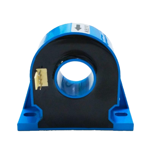
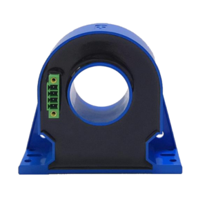
Like conventional current sensors, general Hall current sensors have four pins, positive (+), negative (-), measuring terminal (M) and ground (0), but wire-line current sensors do not have these four pins. , but there are three leads of red, black, yellow and green, which correspond to the positive pole, negative pole, measuring terminal and ground respectively. At the same time, there is an inner hole in most sensors, and the wire should pass through the inner hole when measuring the primary current. The size of the aperture has an inevitable relationship with the product model and the size of the measured current.
Regardless of the type of current sensor, the wiring of the pins should be connected according to the conditions noted in the manual during installation.
1) When measuring alternating current, it is mandatory to use a bipolar power supply. That is, the positive pole (+) of the sensor is connected to the “+VA” terminal of the power supply, and the negative pole is connected to the “-VA” terminal of the power supply. This connection is called a bipolar power supply. At the same time, the measurement terminal (M) is connected to the “0V” terminal of the power supply through a resistor (single finger zero magnetic flux type).
2) When measuring DC current, a unipolar or single-phase power supply can be used, that is, the positive pole or negative pole is short-circuited with the “0V” terminal, so that only one electrode is connected.
In addition, the use, model, range, and installation environment of the product must be fully considered during installation. For example, the sensor should be installed in a place that is conducive to heat dissipation.
In addition to installing wiring, instant calibration and calibration, and paying attention to the working environment of the sensor, you should also pay attention to the following items to ensure the test accuracy:
1) The primary wire should be placed in the center of the inner hole of the sensor, and should not be biased as far as possible;
2) Fill the inner hole of the sensor as completely as possible with the primary wire, without leaving any gaps;
3) The current to be measured should be close to the standard rated value IPN of the sensor, and the difference should not be too large. If the conditions are limited, there is only one sensor with a high rated value at hand, and the current value to be measured is much lower than the rated value. In order to improve the measurement accuracy, the primary wire can be wound several times to make it close to the rated value. For example, when a sensor with a rated value of 100A is used to measure a current of 10A, in order to improve the accuracy, the primary wire can be wound ten times around the center of the inner hole of the sensor (in general, NP=1; in one circle in the inner hole, NP= 2;…;Nine circles, NP=10, then NP×10A=100A is equal to the rated value of the sensor, which can improve the accuracy).
Will the Hall current sensor experience magnetic saturation?
what is magnetic saturation phenomenon?
A ferromagnetic or ferrimagnetic substance is in a state where the magnetic polarization or magnetization does not increase significantly with the increase of the magnetic field strength.
Due to the limitation of the physical structure of the magnetic permeable material, the passing magnetic flux cannot increase infinitely. No matter you increase the current or the number of turns, the magnetic flux passing through a certain volume of magnetic permeable material will no longer increase to a certain amount, and the magnetic saturation will be reached. .
Suppose there is an electromagnet, when a unit current is applied, the magnetic field strength generated is 1, when the current increases to 2, the magnetic field strength will increase to 2.3, when the current is 5, the magnetic field strength is 7, but the current reaches 6 When the magnetic field strength is still 7, if the current is further increased, the magnetic field strength is 7 and no longer increases. At this time, it is said that the electromagnet has magnetic saturation.
Magnetic saturation hazards
The interior of the Hall current sensor includes high magnetic permeability materials. After the high magnetic permeability materials are magnetically saturated, the secondary current (or voltage) of the sensor will no longer change according to the change of the primary current, resulting in measurement errors or protection failures of the secondary circuit. Temporary magnetic saturation may also cause excessive heating of the magnetic conductive material and damage the insulation between the primary circuit and the secondary circuit of the Hall current sensor, endangering equipment and personal safety.
Hall current sensor magnetic saturation problem
Many Hall current sensor manufacturers also promote the absence of magnetic saturation as an important advantage of Hall current sensors in their technical materials. The absence of magnetic saturation of the Hall current sensor is almost one of the main advantages of the Hall current sensor that has been widely recognized since its application.
Is this the truth?
In fact, the Hall current sensor contains a non-linear magnetic core, which already determines that the Hall current sensor will be magnetically saturated under certain circumstances!
Magnetic Saturation Problem of Open-loop Hall Current Sensor
The figure below is a schematic diagram of the typical magnetization curve of all high magnetic permeability materials:
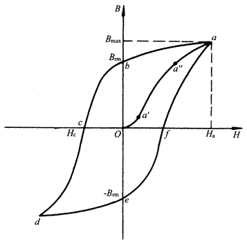
In the figure, Oa’ is the initial nonlinear segment, a’a” is the linear segment, and a”a is the saturation region. As we all know, in order to obtain better measurement results, whether it is an open-loop Hall current sensor or an electromagnetic transformer, a section with better linearity in the magnetization curve will be used as the working range. In other words, as long as the magnetic induction exceeds a certain range in the linear region, magnetic saturation will occur.
Compared with the electromagnetic transformer, there is only one reason for the magnetic saturation of the open-loop Hall current sensor, that is, the primary current is large enough.
It will not cause magnetic saturation due to low current frequency, which is the advantage of the Hall current sensor and also the magnetic saturation characteristic of the open-loop Hall current sensor.
In contrast, the electromagnetic transformer also has an advantage, that is, the secondary load is small enough, even if there is a lot of overload, magnetic saturation will not occur.
Magnetic Saturation Problem of Closed-loop Hall Current Sensor
The magnetic saturation problem of the open-loop Hall current sensor is relatively simple. In contrast, the magnetic saturation problem of the closed-loop Hall current sensor seems incomprehensible, because the magnetic flux in the magnetic core is zero when the closed-loop Hall current sensor works normally. , under zero magnetic flux, naturally it will not be saturated.
However, this will only be possible under normal working conditions!
In fact, even if the electromagnetic current transformer or open-loop Hall current sensor magnetic saturation problem occurs under abnormal working conditions such as overload, low frequency, and heavy load, it will not occur under normal working conditions. Magnetic saturation!
It can be seen from the working principle of the closed-loop Hall current sensor that zero magnetic flux is established on the premise that the magnetic field generated by the secondary side compensation winding can offset the magnetic field generated by the primary side conductor. So, can the closed-loop Hall current sensor maintain this zero flux under any circumstances?
Obviously not!
A. When the sensor is not powered, the secondary side compensation winding does not generate current. At this time, the closed-loop Hall current sensor is equivalent to an open-loop Hall current sensor. As long as the primary current is large enough, magnetic saturation will occur.
B. Normal power supply, but the primary current is too large. This is because the current that the secondary compensation winding can generate is limited after all. When the magnetic field generated by the primary current is greater than the maximum magnetic field that the secondary compensation winding can generate, the magnetic balance is broken, and a magnetic field passes through the magnetic core. When the current continues to increase, the magnetic field in the magnetic core also increases. When the primary current is large enough, the closed-loop Hall current sensor enters a state of magnetic saturation!
Compared with electromagnetic current transformers and open-loop Hall current sensors, magnetic saturation of closed-loop Hall current sensors is less likely to occur, but it does not mean that it will not occur. Improper use or long-term overload can also cause magnetic saturation.